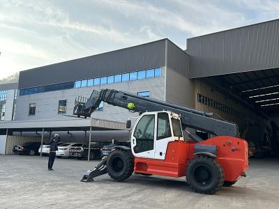
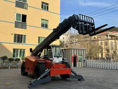
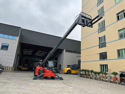
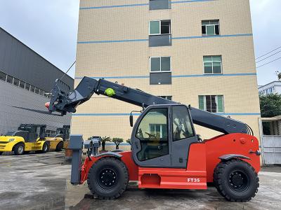
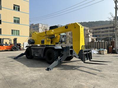
Parts composition and principle of Rough Terrain Forklift Truck braking system
1. Brake control components:
1. Hydraulic Diesel Forklift brake drum; 2. Brake cam; 3. Brake shoe; 4. Rod; 5. Steering rod; 6. Return spring; 7. Pedal. When the brake pedal is applied lean, the brake shoes are connected to the brake drum attached to the forklift's drive motor. Then complete the braking operation.
2. Service brake 1. Brake pedal; 2. Spring; 3. Oil cylinder; 4. Brake shoe; 5. Drive motor; 6. Brake drum; 7. Fluid storage tank. The brake fluid is stored from a distance. Liquid tank; 7. The liquid flows out and is replenished into the main oil cylinder (3).
3. There is a piston in the master cylinder, which can push the brake fluid into the brake pipeline. The fluid reservoir located on the fairing is connected to the inlet of the main cylinder. The oil supply line keeps the master cylinder (3) full and no air enters the system. Reservoir (7) supplies brake fluid to the system. When the brake pedal is first pushed, the piston moves toward the master cylinder and pushes brake fluid into the brake line. When the floating piston is pushed into the piston on the isolation layer, the liquid in the piston rotates around the cup seal and flows out through the floating piston and the output. This action will continue until the liquid pressure in the piston bore reaches the opening overflow. valve pressure. The liquid pushed into the piston has returned to the reservoir (7). Cup seal, barrier and piston fluid is pushed through the piston and outlet. The forced fluid travels through the brake lines to the steering wheel cylinder in the brake assembly. A check valve in the master cylinder maintains a small amount of pressure in the brake line when the pedal is released. This small amount of pressure helps the brake components push air out of the brake system.


